DiscreteVic's Homepage
Bookmark this to keep an eye on my project updates!
MOS6507 - Internal Bus specification
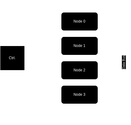
Architecture
The bus traffic is controlled by a controller that manages how data flows between the nodes.
The data bus width is 8 bits, and 1 byte is transmitted each time.
The bus allows three states: Logic 0, Logic 1, and Z (high impedance).
Every communication over the bus is half-duplex.
The clock signal is shared between every component.
Components
- Controller:
It is responsible for selecting the nodes involved in the data exchange.
The direction (read/write) of each node is configured by the controller.
The controller is not connected to the data signals.
- Nodes:
Connected to the controller and to the data bus.
They can have three states in each transmission: passive (not involved), write (send data), or read (receive data).
The default state is passive.
The nodes can be unidirectional(write) or bidirectional(write and read).
In each transmission there is one exclusive write node simultaneous.
Signals
- Control (Controller -> Node):
Enable [1 bit] -> “0”: (default) Pasive, not involved at communication, every signal remains ‘Z’(high impedance). “1”: Active, Write to data bus.
Load [1 bit] -> “0”: (default) Pasive, not involved at communication. “1”: Active, Reads from data bus. Required just for bidirectional nodes.
- Data (Node <-> Bus):
Signal of 8 bit width, the value depends of the control signals.